

Firstly, it helps to prevent any accidental shorts circuit between the battery and the vehicle body. There are a few reasons for this convention. This is because most vehicles are “negative earthed” – that is, the body of the vehicle is connected to the negative terminal of the battery. When connecting a battery isolator to your vehicle, the convention is to put the isolator on the negative lead. It turns off when the isolator is protecting your starting battery.ĭo You Put A Battery Isolator On Positive Or Negative? A green light indicates proper operation. Step-15: Remove the negative probe from the battery and place it on your ground point. Step-14: Make sure all your connections are safe and tight, then test for a proper ground by placing the voltmeter probe on the positive and negative auxilary battery terminals and note the reading. Step-13: Leave a green LED light on to indicate proper installation. Step-12: Finally, attach the 12in black cable to the negative lead on the auxilary battery, then attach the other end and the vehicle’s negative cable to the starter battery’s negative lead. Step-11: Then attach the 24in red cable from the isolator and the vehicle’s positive cable to the positive lead on the starter battery. Step-10: Attach the 12in red cable from the isolator to the positive lead on the auxilary battery. Step-09: Attach the ground wire from the unit to a bare metal spot close to the battery.
12V BATTERY ISOLATOR SWITCH INSTALL
This will hide them both and install it to the mounting plate with the two remaining longer 38mm screws. The other 12in red cable attaches to the remaining underside bolt. Step-08: Having done that, attach the end of the 24in red cable to the underside bolt. Step-07: Test the fitment in progress to determine wire runs and which of the eight base punch outs will be used in your configuration. Step-06: Install the insulated ring terminal on the black ground wire attached to the isolator unit. Prep it and use a moderate heat source to shrink the including cover. Step-05: Strip 15 to 20mm of the unterminated end of the 24in red cable and install one of the two lug connectors provided. Step-04: Attach the mounting plate to your chosen location. Drill the holes following the template you made using the two 19mm screws included. Step-03: Remove the lower mounting plate from the unit and use it as a template for marking the board. Avoid placement near hot exhausts and keep it as close to the starter battery as possible, preferably where it’s LED can be seen. Each vehicle is different, so the location point is important. Step-02: Install your auxilary battery next to your starter battery. Step-01: Locate the battery on your vehicle and disconnect the negative wire first for safety, then the positive wire.
12V BATTERY ISOLATOR SWITCH HOW TO
This article will help you understand how to hook up a battery isolator so that you can get the job done right. It’s not an easy task, and it can be frustrating trying to figure out how to do it. If you’re like most people, you’ve probably struggled to hook up a battery isolator. Step By Step Procedure For Hooking Up A Battery Isolator

How To Install A Battery Isolator Switch On A Boat?.Where Can I Find A Dual Battery Isolator Wiring Diagram?.How Do I Wire A 12V Battery Isolator Diagram?.Why Put A Battery Isolator Switch On The Negative Terminal?.

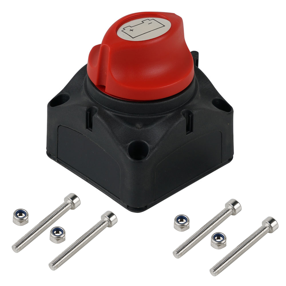
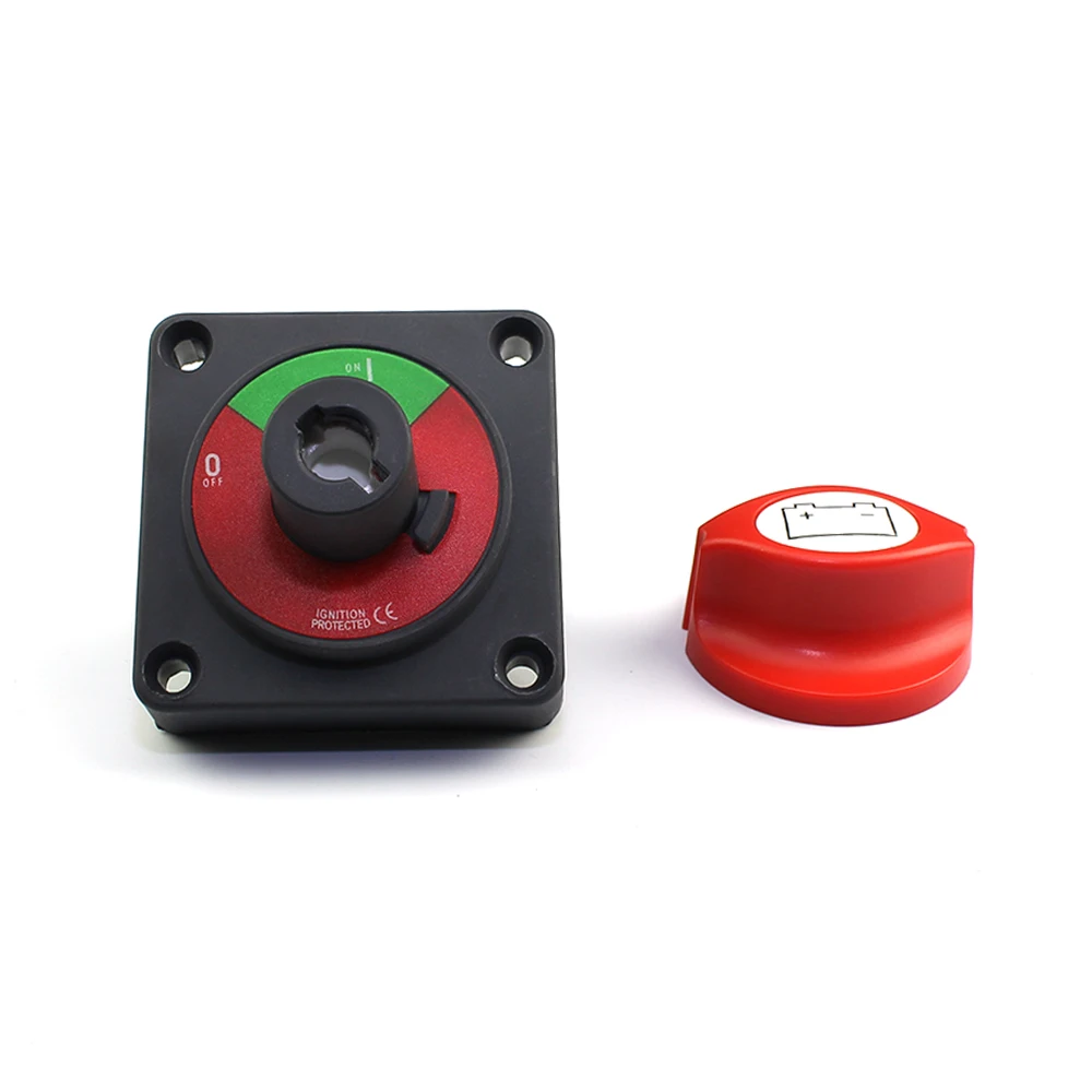
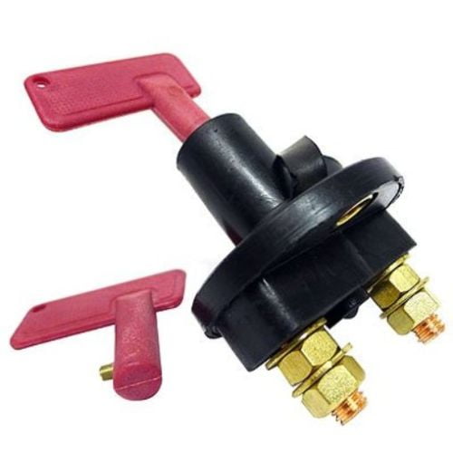
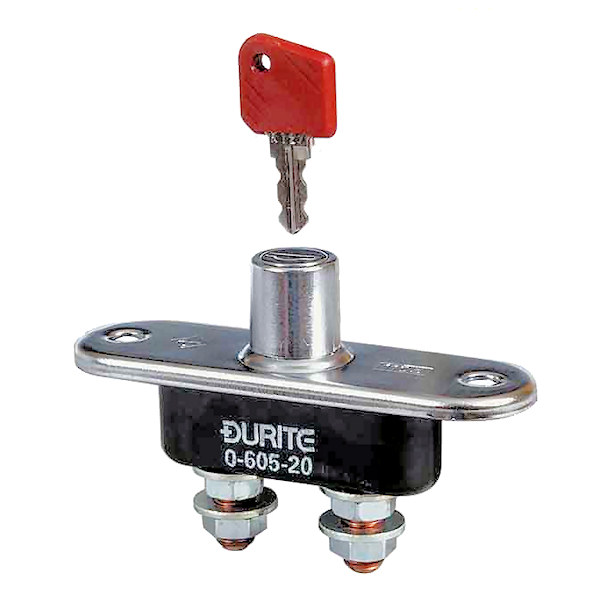
How Do You Wire A Battery Isolator Switch?.Do You Put A Battery Isolator On Positive Or Negative?.Step By Step Procedure For Hooking Up A Battery Isolator.: Eliminate any power consumption of the battery when the vehicle or boat is not in use, and disconnect the battery safely. :2 x 10mm (3/8 inch), very easy to install, Tin plated copper studs and nuts ignition protected : used for DC 12-48 V system isolation and protection of electrical systems, can be independent or locked together with other switches. : High-quality battery isolation switches are very easy to install, widely used for car, marine boat, RV, camper, travel trailer, truck, ATV, UTV, battery banks and other devices. : On/Off 2 positions, 275 A continuous at DC 12V, 455 A intermittent at DC 12V, 1250 A momentary at DC 12V. : ABS plastic housing, durable made for safety use, rear cover insulates terminals against any short of circuits, equipped with 4 sets of bolts.


 0 kommentar(er)
